
Force Measurement Tips
Micro-force sensors on PCB supports — the calibrated tips for the Force Measurement System and SFAFM platform.
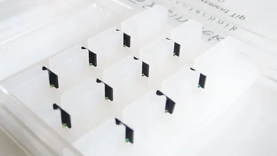
A calibrated spring, not just a probe#
Force Measurement Tips are piezo-resistive cantilever sensors — the FMT-120 in particular carries a tip radius under 20 nm and a calculated force constant of 30 to 40 N/m, so the whole assembly behaves as a proof mass on a known spring: deflection converts directly into force. The sensor bridge reads out at 18.8 × 10⁻³ mV/nm for a bridge voltage of 2.5 V, and its own resistance runs 500 to 650 Ω — the figures the Force Measurement System’s electronics are built around.
Headroom before the tip lets go#
Assuming a 10% deflection and the lowest force constant in the range, the tip is rated to a maximum force of 360 µN before contact is lost — enough range to cover most push, pull and contact measurements without swapping to a stiffer sensor. The same piezo-resistive bridge reports resonance as well as static force, so one tip covers both a force curve and a frequency-domain measurement.
The consumable front end#
Mounted on a small PCB support, each tip drops straight into the Force Measurement System or the SFAFM platform. When a tip’s spring constant drifts or its edge wears in service, you swap the PCB rather than recalibrating the whole setup.
Gallery
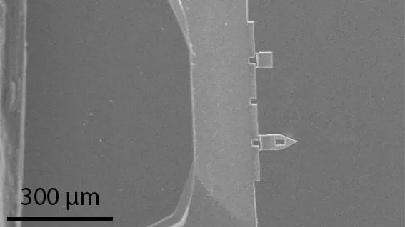
Two FMT cantilevers on the PCB edge — 300 µm scale bar. 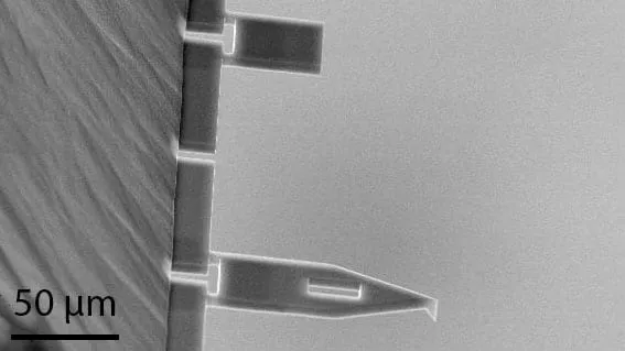
A closer pair of cantilever sensors — 50 µm scale bar. 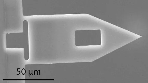
A single FMT-120 cantilever, tip radius under 20 nm — 50 µm scale bar. 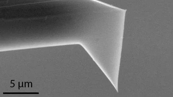
The cantilever tip apex — 5 µm scale bar.
Technical data
FMT-120 sensor
- Tip radius
- < 20 nm
- Tip force constant (calculated)
- 30 to 40 N/m
- Maximum tip force
- 360 µN
- Resistance
- 500 to 650 Ω
- Sensitivity
- 18.8 × 10⁻³ mV/nm at Vbridge = 2.5 V
Sensing principle
- Technology
- Piezo-resistive, force and resonance feedback
Related products & accessories
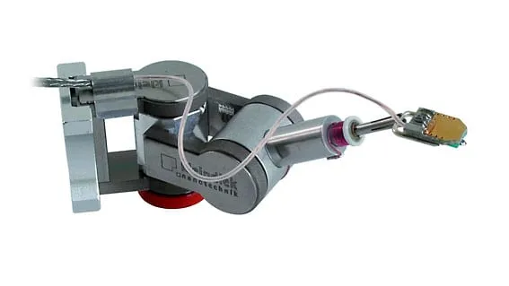
Force Measurement System FMS
Laser-free force measurement and nanoindentation in the SEM — resolve forces to 10 nN and identify materials by their resonance.
View product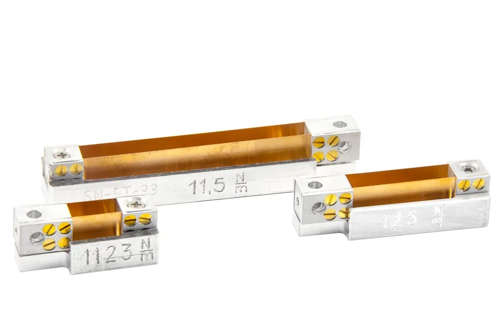
SpringTable & Force Measurement Analysis
A low-tech SpringTable that converts the SEM's own resolution into quantitative force–distance curves.
View productTalk to an application engineer
Tell us your sample and your microscope — we’ll walk you through the workflow and route you to the right regional team.